


Wire, Cable & Fiber Extrusion Filtration: The Complete Guide
Wire, cable, and fiber extrusion require the finest melt filtration specifications in thermoplastics processing. Fiber spinning demands sub-70 μm filtration to protect spinnerets from micro-contaminants that cause filament breaks; cable insulation extrusion requires defect-free melt to prevent voids and pin-holes that fail electrical testing. Both applications require continuous self-cleaning filtration — at 270–400 mesh (37–53 μm), screen pack saturation occurs too rapidly for manual changes to be operationally sustainable.
Why Wire, Cable, and Fiber Extrusion Set the Highest Filtration Standards
Wire, cable, and fiber extrusion share a defining characteristic that sets them apart from film, sheet, and pipe applications: the die geometry is extremely small relative to the melt volume processed. A spinneret for multifilament fiber production contains hundreds or thousands of holes with diameters of 0.2–0.8 mm. A cable insulation die has a thin, precision-machined annular gap of 0.5–3 mm. Any solid particle that reaches these dies either blocks a hole — causing a filament break or a surface defect — or creates a localised restriction that distorts the geometry of the entire cross-section.
The consequence is that filtration fineness requirements in these applications are the strictest in polymer extrusion. Where blown film operates comfortably at 100–200 mesh (74–149 μm), fiber spinning requires 270–400 mesh (37–53 μm) and fine denier multifilament may require sub-30 μm filtration. At these mesh counts, differential pressure (ΔP) across the screen pack rises significantly faster than in film applications — making the choice of screen changer technology a critical process engineering decision, not an ancillary equipment specification.
According to the Society of Plastics Engineers (SPE), filament breaks in fiber spinning are among the top three causes of production loss and quality rejection — and the majority trace to contamination events above the spinneret’s critical particle threshold. For cable insulation, the International Electrotechnical Commission (IEC) testing standards for voltage breakdown and dielectric strength are particularly sensitive to voids and inclusions in the insulation wall — both of which originate from melt contamination reaching the die.
The Shared Challenge: Rapid Screen Saturation at Fine Mesh
The engineering challenge in wire, cable, and fiber filtration is not achieving the required fineness — it is sustaining it in production. A 325-mesh screen pack (44 μm aperture) on a multifilament spinning line running 200 kg/h of nylon 6 accumulates pressure differential at a rate that makes screen life typically 2–6 hours. Three to twelve manual screen changes per 8-hour shift is not an operational model — it is an operational crisis.
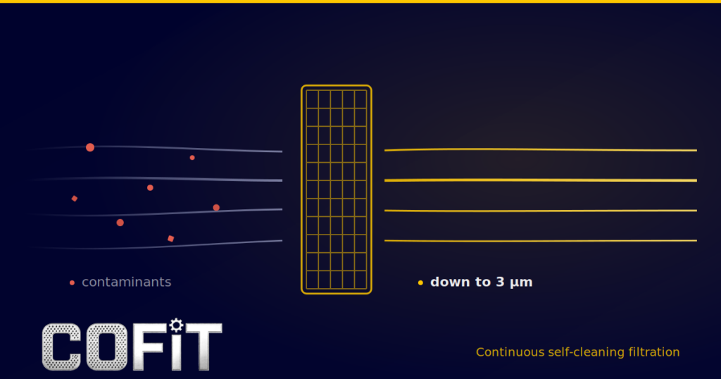
Continuous self-cleaning filtration resolves this by cleaning the screen in place before it approaches saturation, maintaining stable filtration area and stable ΔP indefinitely. The AP Series operates at any filtration fineness down to 3 μm, continuously, without production interruption. For wire and fiber lines, this is not an efficiency upgrade — it is the engineering prerequisite for running fine filtration at all.
Fiber Spinning: Melt Filtration Requirements by Application
Fiber spinning encompasses a wide range of polymer types and end-use applications — from commodity polyester staple fiber to high-tenacity industrial yarn and ultra-fine microfiber. Each application has a distinct filtration requirement driven by the spinneret geometry, the target fiber denier, and the end-use quality specification. The table below maps the principal fiber applications to their filtration specifications.
| Application | Polymer | Fiber denier | Mesh range | Aperture (μm) | Critical requirement |
|---|---|---|---|---|---|
| Polyester staple fiber | PET | 1.5–6 dpf | 200–270 mesh | 53–74 μm | Spinneret protection, filament uniformity |
| Polyester multifilament (textile) | PET | 0.5–3 dpf | 270–325 mesh | 44–53 μm | Zero filament breaks, tenacity consistency |
| Nylon 6 / Nylon 6,6 multifilament | PA6, PA66 | 1–5 dpf | 270–400 mesh | 37–53 μm | Spinneret protection, dye uniformity |
| Polypropylene spunbond / nonwoven | PP | 1.5–4 dpf | 200–270 mesh | 53–74 μm | Web uniformity, filament continuity |
| Microfiber / ultra-fine filament | PET, PA | <0.5 dpf | 400+ mesh | <37 μm | Extreme spinneret protection — any inclusion fatal |
| Industrial yarn (tyre cord, seatbelt) | PET, PA66 | 5–10 dpf | 250–325 mesh | 44–63 μm | Tensile strength consistency, zero breaks |
Aperture values based on ASTM E11 plain weave nominal specification. dpf = denier per filament.
Why Spinneret Protection Requires Continuous Filtration
A multifilament spinneret contains 50–1,000 holes depending on the yarn count and configuration. Each hole is machined to within ±1–2 μm of the specified diameter. A single contamination particle above the critical threshold — typically 40–60% of the hole diameter — blocks the hole and severs the filament. On a 500-hole spinneret, one blocked hole reduces productivity by 0.2% and creates a quality defect in the yarn bundle. Ten blocked holes constitutes a product failure.
The rate at which a 325-mesh screen pack saturates on a fiber spinning line makes manual screen changing operationally impossible above a certain throughput. At 300 kg/h of PET multifilament with standard batch resin, screen life at 325 mesh is typically 3–5 hours. A line running 20 hours per day would require four to seven screen changes daily — each taking 20–40 minutes and generating scrap during the pressure recovery and re-stabilisation phase.
“On our nylon multifilament line, we switched to continuous self-cleaning filtration after calculating that manual screen changes were costing us 18% of annual capacity,” notes a process engineer at a European technical fiber producer. “The first month after installation, filament break rate dropped by 35% — attributable directly to the elimination of pressure spikes at screen changes.”
Wire & Cable Insulation Extrusion: Filtration for Electrical Performance
Cable insulation extrusion applies a thin layer of thermoplastic insulation — typically PVC, PE, XLPE, PP, or fluoropolymer — over a conductor. The insulation wall thickness ranges from 0.2 mm for fine magnet wire to 5–20 mm for power cable. In all cases, the electrical performance of the finished cable depends entirely on the dielectric integrity of the insulation — and dielectric integrity is compromised by any void, inclusion, or contamination event in the melt that reaches the crosshead die.
IEC 60227 and IEC 60502 testing standards for low and medium voltage cables specify voltage breakdown tests that are sensitive to inclusions as small as 50–100 μm in the insulation wall. For high-voltage cable (HV/EHV), IEC 60840 and IEC 62067 impose even stricter contamination limits — inclusions above 25–50 μm in XLPE insulation are documented as partial discharge initiation sites that cause long-term electrical degradation. According to the Cable & Wire Technology International industry review, contamination-related insulation failures account for a significant portion of manufacturing scrap in high-voltage cable production.
Screen Pack Specification for Cable Insulation by Application
| Cable type | Insulation material | Mesh range | Aperture (μm) | Key standard |
|---|---|---|---|---|
| Low voltage power cable | PVC, XLPE | 150–200 mesh | 74–105 μm | IEC 60227 / IEC 60502 |
| Medium voltage cable | XLPE, EPR | 200–250 mesh | 53–74 μm | IEC 60502-2 |
| High voltage cable (HV) | XLPE (ultra-clean) | 250–325 mesh | 44–63 μm | IEC 60840 |
| Extra-high voltage (EHV) | XLPE (super-clean) | 325–400 mesh | 37–44 μm | IEC 62067 |
| Telecom / data cable jacket | PE, PVC, LSZH | 150–200 mesh | 74–105 μm | IEC 60794 |
| Magnet wire enamel wire | Polyamide-imide, Polyester | 200–270 mesh | 53–74 μm | IEC 60317 |
XLPE for High-Voltage Cable: The Most Demanding Filtration Environment
Ultra-clean XLPE (cross-linked polyethylene) for high and extra-high voltage cable represents the most demanding melt filtration environment outside of medical-grade plastics processing. Partial discharge inception voltage (PDIV) — the threshold at which electrical discharges begin in the insulation — is directly correlated with the size distribution of contamination particles in the insulation wall. A single contamination particle above 100 μm in a 110 kV cable insulation wall reduces the expected service life by years.
HV cable insulation is produced under ultra-clean room conditions equivalent to ISO Class 5–6 manufacturing environments. The melt filtration system is the last mechanical barrier between the polymer and the die, and must operate at 325–400 mesh (37–44 μm) continuously without any pressure events that could introduce stagnant melt zones — the primary source of carbonised particles in thermally sensitive XLPE compounds. Continuous self-cleaning filtration, with its elimination of dead zones and pressure spikes, is the only compatible filtration technology for EHV cable production.
What Is Your Screen Change Frequency Costing You?
Enter your fiber or cable line throughput, screen change frequency, and shift schedule. The Cofit Productivity Savings Calculator shows your monthly output loss and annual revenue impact in under two minutes.
Screen Changer Selection for Wire, Cable, and Fiber Lines
The filtration fineness required for wire, cable, and fiber applications — 200 to 400+ mesh — eliminates discontinuous screen changers as a practical option above moderate throughputs. At 325 mesh, the pressure cycle from a clean screen to saturation on a fiber spinning line running 200 kg/h of polyester is typically 3–5 hours. At three changes per 8-hour shift, the line loses 60–120 minutes of production daily to screen changes and restart stabilisation — a rate that is economically and operationally unsustainable for 24/7 production.
Continuous self-cleaning filtration is therefore the standard technology for all high-throughput fiber spinning, cable insulation, and wire coating lines. The continuous vs discontinuous screen changer guide covers the decision framework in detail — for wire, cable, and fiber at standard throughputs, the decision is effectively made by the application requirement.
The No-Hydraulic-Unit Advantage for Fiber and Cable Lines
Fiber spinning and cable insulation extrusion lines are typically space-constrained: multiple extruders, godets, quench baths, and winders occupy the available floor area. The absence of a hydraulic power unit requirement in the AP Series — unlike many competing continuous screen changer designs — is operationally significant in retrofit situations where utility connections and floor space are fixed constraints.
For high-voltage cable insulation in particular, the elimination of hydraulic actuation in the melt zone removes the risk of hydraulic fluid contamination — a contamination source that is incompatible with the cleanliness requirements of EHV cable production regardless of seal quality or maintenance programme.
Melt Pressure Stability and Its Effect on Fiber Denier and Cable Wall Thickness
Melt pressure instability from screen pack saturation affects wire and fiber products in the same way it affects film — through dimensional variation. In fiber spinning, pressure variation upstream of the spinneret produces denier variation across the filament bundle. In cable insulation, it produces wall thickness variation around the circumference of the cable. Both are quality failures: denier variation causes uneven dyeing in textile fiber; wall thickness variation in cable insulation creates thin spots that reduce breakdown voltage below specification.
According to SPE technical data, ±5% upstream pressure variation produces measurable dimensional variation in fiber denier and cable wall thickness equivalent to the same relationship documented for film gauge variation. Continuous self-cleaning filtration — maintaining melt pressure within ±2% — reduces these dimensional variations to below the detection threshold of standard quality inspection systems.
The Economics of Filtration on Fiber and Cable Lines
The economic case for continuous filtration on fiber and cable lines is driven by three components: direct downtime from screen changes, scrap generated during pressure stabilisation after each change, and quality rejects from filament breaks or cable insulation defects caused by pressure instability.
According to Plastics Technology, unplanned extrusion downtime costs $200–$500 per line-hour. A nylon multifilament spinning line running 300 kg/h, three shifts per day, with four manual screen changes per shift at 25 minutes each loses 300 hours of production per year. At $3.00/kg output value for textile-grade nylon multifilament, the annual direct downtime cost reaches $270,000 — before filament break scrap and quality rejects.
Filament break scrap during screen change pressure events is a significant secondary cost in fiber spinning. Each pressure spike at a manual screen change can cause 5–15 minutes of abnormal running — during which filament break rate rises significantly and the output must be segregated as downgraded or waste material. On a 300 kg/h line, 10 minutes of break-related scrap per screen change × 12 changes per day × 250 days = 2,083 hours of downgraded output per year.
Cofit AP Series for Wire, Cable, and Fiber Extrusion
The AP Series continuous self-cleaning screen changer is the filtration solution for fine-filtration applications in fiber spinning, cable insulation, and wire coating — where sustained operation at 200–400+ mesh without production interruption is the engineering requirement.
- Fiber spinning: polyester, nylon, polypropylene — all denier ranges
- Cable insulation: PVC, XLPE, PE, PP, LSZH — LV through EHV grades
- Wire coating: magnet wire, automotive wire, data cable
- Max operating pressure: 500 bar · Max temperature: 350°C
- Throughput: 5–2,000 kg/h · Cleaning trigger: ΔP or timer
Frequently Asked Questions
Filtration fineness for fiber spinning depends on the fiber denier and spinneret geometry. Standard polyester staple fiber (1.5–6 dpf) requires 200–270 mesh (53–74 μm, ASTM E11). Multifilament textile grades (0.5–3 dpf) in polyester and nylon require 270–325 mesh (44–53 μm). Microfiber and ultra-fine filament below 0.5 dpf require 400+ mesh (below 37 μm). Industrial yarn for tyre cord and seatbelt applications — where tensile consistency is critical — specifies 250–325 mesh (44–63 μm). The critical constraint is always the spinneret hole diameter: particles above approximately 40–60% of the hole diameter risk blocking individual holes and causing filament breaks. For mesh-to-micron conversions across all these specifications, see the Cofit Mesh-to-Micron Converter.
At the filtration fineness required for fiber spinning (270–400 mesh) and high-voltage cable insulation (250–400 mesh), screen pack saturation occurs in 2–6 hours at typical production throughputs. At four screen changes per 8-hour shift, a fiber spinning line loses 60–100 minutes of production daily to changeover and stabilisation. Continuous self-cleaning filtration maintains a constant filtration area and stable melt pressure without any production stops — for fine filtration applications, this is not an efficiency preference, it is the engineering prerequisite for sustaining production. Manual screen changing at 325 mesh is operationally viable only on very low throughput or development lines.
Melt pressure instability from screen pack saturation produces denier variation across the filament bundle in fiber spinning — analogous to gauge variation in film extrusion. Rising ΔP as the screen saturates reduces effective melt pressure at the spinneret, lowering the output rate per hole and producing finer-than-specified filaments. When the screen is replaced and pressure restores, the output rate increases and filaments become coarser. The result is a denier variation pattern along the yarn length that causes uneven dyeing in textile applications and tensile inconsistency in technical yarn. According to SPE data, ±5% upstream pressure variation produces measurable dimensional variation equivalent to the gauge variation relationship in film. Continuous self-cleaning filtration holds melt pressure within ±2%, eliminating this variation source.
High-voltage (HV) and extra-high voltage (EHV) cable insulation — typically ultra-clean XLPE — requires 325–400 mesh filtration (37–44 μm) under ISO Class 5–6 cleanroom manufacturing conditions. IEC 60840 and IEC 62067 testing standards require voltage breakdown performance that is directly degraded by contamination particles above 25–50 μm in the insulation wall. These particles act as partial discharge (PD) initiation sites that reduce service life by years. Beyond filtration fineness, HV cable production also requires elimination of melt stagnation zones — the source of carbonised particles from thermal degradation — which makes continuous self-cleaning filtration doubly essential: it provides fine filtration AND eliminates the dead zones in the screen changer housing where thermal degradation occurs during conventional screen change events.
Yes, in most cases. The AP Series installs in the same position as an existing screen changer or breaker plate assembly — between the extruder barrel outlet and the die adapter or crosshead — without modifications to the extruder or die. The flange geometry must be confirmed against the existing line drawings before specifying the replacement unit. The AP Series does not require a hydraulic power unit, which significantly simplifies retrofit installation on lines where floor space and utilities are constrained. A Cofit process engineer reviews line geometry and specifies the correct configuration before any equipment is ordered. Installation on a planned maintenance weekend is typical where flange compatibility is confirmed.
Sources and References
- Society of Plastics Engineers (SPE) — filament breaks as top-three cause of production loss in fiber spinning; melt pressure variation → dimensional variation relationship
- International Electrotechnical Commission (IEC) — IEC 60227, IEC 60502, IEC 60840, IEC 62067: voltage breakdown and dielectric standards for cable insulation contamination limits
- Cable & Wire Technology International — contamination-related insulation failures in high-voltage cable production
- Plastics Technology — extrusion downtime cost ($200–$500/line-hour)
- ASTM E11 — wire mesh aperture specifications (mesh count to micron conversion)
- European technical fiber producer operating data — 35% filament break reduction and 18% capacity recovery after switching to continuous self-cleaning filtration
- Cofit International engineering data — AP Series: filtration fineness down to 3 μm, melt pressure stability ±2%, max operating pressure 500 bar, max temperature 350°C
Find Out What Screen Changes Are Costing Your Fiber or Cable Line
Enter your throughput, screen change frequency, and shift schedule. The Cofit Productivity Savings Calculator shows your monthly output loss and annual revenue impact in under two minutes. Or speak directly with a Cofit engineer about filtration specification for your application.
Cofit deals with research, engineering, manufacture and distribution of automatic and continuous screen changers for post-consumer and post-industrial recycling materials too.
Contact us to upgrade your extrusion system, ask us for more info about any product or service.